Calibrating the outputs
Introduction to calibration
Creating a setup in EdgeTX is a story of two parts.
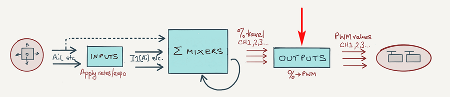
The first part is about the mixers - how stick commands are converted to mixer values. In the diagram above, it's everything to the left of the outputs.
The second part - and the subject of this article - is about Outputs calibration. This deals with your model's geometry and mechanical imperfections. Think of it as a super-sophisticated servo programmer, and you have the idea! Technically, it maps mixer values (as shown in the Mixers monitor) to PWM values (as shown in the Outputs monitor).
Why bother with calibration?
Calibrating your setup provides several benefits:
- It allows you to set absolute limits for each servo, to avoid any possibility of damage to linkages.
- It compensates for geometrical differences between left and right sides
- It allows you to employ identical weights for left- and right-side mixers, which allows for some cool optimisations in your setup.
- It allows you to distinguish between (unwanted) servo drift and (wanted) trim offsets.
- It offers precise tracking of flaps throughout their travel.
- It allows you to replace a servo on the field, with minimum re-adjustment.
The Outputs menu
Calibration is performed in the Outputs menu, so let's take a quick look at the various fields.
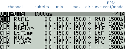
Outputs menu
The key fields are as follows:
- Min - servo end point 1 (when mixer value = -100% )
- Max - servo end point 2 (when mixer value = +100%
- Subtrim - servo centre (when mixer value = 0%)
- Dir - servo direction
- Curve - response curve (alternative to Min/Max/Subtrim)
- Subtrim mode - use delta mode (so adjusting subtrim does not affect the end points)
To make calibration possible your setup should be able to supply mixer values of +/-100% to each output. Then you adjust Min, Max, Subtrim - or Curve - as required.
Prerequisites
In order to perform a calibration the following will be needed::
- The actual model (obviously!)
- A way to generate mixer values of −100%, 0% and +100%. These are the 'reference' values needed to visualise the calibrated limits and centres.
My Calibration Mode allows you to generate these values on demand, using the gimbals.If you can't implement a Calibration mode, then you can get a similar result by (a) setting the input and mixer weights to 100%, and (b) centring the trims. However, this method is not practical after you've finalised your rates and trims (as we'll see, it's useful to be able to check calibration at intervals during the lifetime of the model).
Calibrating ailerons, elevator, rudder, V-tail
Calibration of these surfaces is simple, but let's spell it out anyway:
- Open the OUTPUTS menu
- Activate Calibration Mode - this will cancel any rates and trims. If you don't have a calibration mode, just set the input and mixer weights to 100%, and centre the trims.
- Adjust Subtrim for correct centre position.
- Adjust Max and Min for each servo:
- First, adjust thee for maximum possible control surface travel
- Next, refine so that control surface travel is equal up/down (or left/right).
- Finally, refine so that left and right surfaces match.
- Exit from Calibration mode. Rates and trim offsets will be restored.
The outputs are now calibrated.
Calibrating flaps (using curves)
Flaps present a greater challenge because (a) they have grossly asymmetric movement (much more down than up) and (b) they have large deflections. This requires (a) a more precise method of calibration using curves, and (b) an offset mix to deal with the asymmetrical movement.
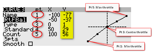
Fortunately OpenTX allows flaps to be calibrated with greater precision by using a curves. To use a curve, you first have to create it in the Curves menu. Then, go the Outputs menu and assign it to the curve field. Once the curve is created, you can edit it by long pressing on the curve field (on most radios).
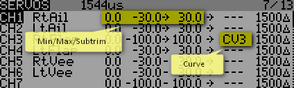
CH1 calibrated via min/max/subtrim
CH3 calibrated via curve
Okay, so let's get back to calibrating flaps! Here's an overview of the procedure:
- Calibrate one flap with a 2-point curve, in other words just set the end points. This flap will act as a reference for the second flap.
- Calibrate the second flap with a 5-point curve, to track the first flap.
- Adjust the flap neutral using an offset mix.
In more detail:
Step 1: set Min, Max and Subtrim to 'pass thru' values
We're going to use curves, so Min/Max and Subtrim must be set to their pass thru values:
- Open the Outputs menu
- For each flap servo, set Min, Max and Subtrim to −100%, +100% and 0% respectively (or -150%, +150% and 0% if using extended limits)..
Step 2: calibrate left flap
Start by calibrating the left flap. The aim is to (a) set the limits of servo movement, and (b) to obtain an approximately linear response. The neutral position is not considered here.- In the Curves menu, create a 2-point curve with points (−100%, -20%) and (100%,20%). The low point values (20%) are to avoid accidental damage to your linkages before finalising the adjustment.
- In the Outputs menu, go to the Curve column, and select the curve you just created
- Enter Calibration mode
- Set the curve points for maximum possible travel, as limited by the linkages. The flap deflection should vary more or less linearly with the calibration input. If necessary, you can add third point aound the middle of the curve.
- Exit the Curve menu
- Exit Calibration mode
Step 3: calibrate right flap
The next task is to synchronise the right flap with the left flap. To achieve the necessary precision, we'll use a 5-point curve.
- In the Curves menu, create a 5-point straight line curve
- In the Outputs menu, go to the Curve column and assign the new curve.
- Enter Calibration mode
- Move the stick to the 0/25/50/75/100 positions; at each position, adjust the corresponding point so that the right flap exactly matches the left flap. (Depending on the linkage geometry, it may be necessary to go back and reduce one or other end point on the left flap.)
- Exit the Curve menu
- Exit Calibration mode
Step 4: create a neutral offset mix
The flap servos are now calibrated, and the flaps should track perfectly. However since the flap has more down-travel than up-, each flap's 'home' position (that is, with the servo at its natural centre position) will be around 30 degrees down. In other words, with all mixers disabled (servos at centre), the flaps will droop 30 degrees!
To fix this we need to apply an offset at the mixer level as follows:
- Exit Calibration mode
- Create a mix in each flap servo channel.
- For each flap mix, set source = 'MAX'. This generates a fixed offset of value 100%.
- Adjust the weights of the mixes, so both flap are at the correct neutral.
All the mixes for roll control, crow, camber and so on will then start from the correct neutral position. The end points of flap travel are not affected - since of course we have already calibrated these in steps 2 and 3.
Adjusting control rates
Once calibration is done, you can finalise the control travel ('rates') as follows:
- For the flight controls (elevator, aileron and rudder): adjust travel in the Inputs menu. Leave mixer weights at 100% (the input weights will propagate to the mixers).
- For all other interactions: adjust the appropriate weights in the Mixer menu. Following calibration, the mixer weights should be equal on the left and right sides.
Using CAL mode to identify servo drift
Most models will suffer during their lifetime from drifting servo neutrals. This may be due to temperature effects, or damaged linkages. Now here's the thing: it can be difficult to distinguish between drift and valid trim offsets which you've dialled in yourself.
However if you calibrate your setup regularly, you can tell the difference. Enter CAL mode, and see if the calibrated centres have changed. If yes, then the servos or linkages have drifted.
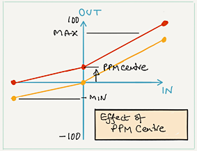
If the amount of drift is small, there's no need to do a complete recalibration, you can simply adjust PPM Centre - the effect is similar to moving the servo arm on its spline. Once you exit CAL mode, all trim offsets will be restored.
So, by calibrating your channels and checking regularly, you can correct for servo drift while at the same time preserving your carefully adjusted trim offsets!
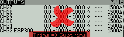
Trims => Subtrims - AVOID!!
OpenTx allows you to re-centre your trims, by moving the offsets to Subtrim. Obviously, using this feature will trash your calibration settings. Avoid!
Calibration-centred design
Even greater benefits can be achieved by designing your setup with calibration in mind from the start. I call this 'calibration-centred design'. The two main elements are:
Integrated CAL flight mode
The first step is to create a CAL mode. That way, you can check the calibration at any time for drifting servos, bent linkages and so on.
GVARs and cascading mixers
A key goal of calibration is to match up left/right outputs. This means that paired mixers can have identical weights, and you can take advantage of this by employing GVARs and cascading mixers in your setup. This will result in:
- single point of adjustment for left/right mixes
- cleaner logic
- reduced data entry errors
Calibration the easy way
All the canned setups published on this site have CAL mode already built-in, protected against accidental operation.
Digging deeper: the mapping layer (advanced)
Okay, we've covered the basics, let's drill down a bit and look at the internal processes.
The Outputs layers is a simple mapping of mixer values to PWM values. In effect, Min, Max and Subtrim define a 3-point curve:
- Min defines the PWM value for a mixer value of −100%
- Max defines the PWM value for a mixer value of +100%
- Subtrim defines the PWM value corresponding to a mixer value of zero.
- Direction reverses the effect
On entry to the Outputs stage, mixer values are clipped to +/−100%. Min and Max therefore represent absolute travel limits. Think of them as electronic end stops.
Conversion of Min/Max/Subtrim % values to PWM units
Min, Max and Subtrim represent PWM values, yet OpenTX displays them as percentages. The conversion is as follows:
- −150% = 732 μs
- −100% = 988 μs
- 0% = 1500 μs
- 100% = 2012 μs
- 150% = 2268 μs
Standard servos have a nominal range of 1000 to 2000μs, so you can think of these percentages as 'percentage of the range of a standard servo - roughly!'.
PWM values outside the range 988 - 2012 μs are only available if the 'extended limits' option is enabled (in the MODEL menu).
Subtrim modes and PPM Centre
The Subtrim mode determines how the limits are calculated. Subtrim mode is set in the Outputs menu (last column). There are two options:
- 'delta' (default) - Limits are defined by Min and Max. Adjusting Subtrim does not affect limits.
- 'equals': Limits are Min +Subtrim and Max + Subtrim, with clipping if the result exceeds Min and Max. Subtrim shifts end points.
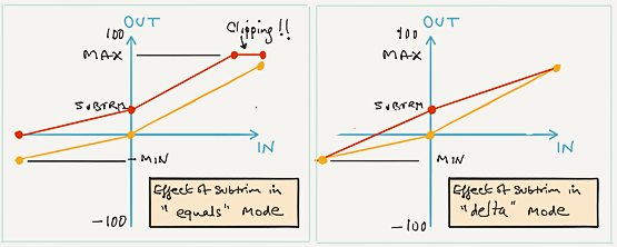
Delta mode is recommended!
Switching between "equals" and "delta" modes will cause the end points to jump, so start with delta mode and stick with it. If later on you need to shift the whole curve with a single adjustment, then use the PPM Centre adjustment. The effect is similar to 'equals' mode.