
Spiral Stability Augmentation with a Piezo-Electric Rate Gyroscope
Summary
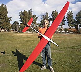
Bill Watson with Emerald used as gyro test bed.
Conventional 6-servo radio controlled thermal sailplanes require active pilot roll input to maintain a constant bank angle in a thermal circle. On their own, the models tend to tighten up the circle and spiral in – they lack "spiral stability" due to the typical low-dihedral wing. An electronic rate gyro is used to sense yaw rate and drives the ailerons to counter this spiral instability. New gyros control the ailerons via two channels, preserving the option of aileron camber changing and "crow". A third input to the gyro provides in-flight adjustment of gyro gain so that fine-tuning is easy.
Spiral Stability
In circling flight, the outboard wing flies faster than the inside wing. Assuming no yaw and no aileron deflection, the outboard wing makes more lift and the model tends to roll in. This effect is maximized at bank angles of about 45 degrees.
Models with substantial dihedral such as rudder and elevator sailplanes counter this effect by their tendency to yaw outboard in circular flight. This yaw in combination with the dihedral increases the angle of attack of the inboard wing relative to the outboard wing, countering the effect of the speed variation over the wing. By tuning the wing dihedral and vertical tail moment arm, any degree of spiral stability can be achieved. More dihedral and longer tail moment arms give more spiral stability. Neutral spiral stability can be achieved by setting:
(EDA) x (Lv / b) / (Cl) = 5.0 approximately.
where:
EDA = equivalent V-dihedral angle in degrees, each wing (see Ref 3).
Lv = vertical tail moment arm (from wing MAC/4 to vertical stabilizer MAC/4)
MAC/4 = quarter chord point of the mean aerodynamic chord
b = wingspan
Cl = lift coefficient while circling (a good guess is 0.6 to 0.9 depending on camber)
Note 1: Lv and b must be in the same units (inches or cm or whatever)
Models with low dihedral will require aileron deflection to avoid rolling in. The alternative to aileron deflection is unacceptably large yaw angles. Aileron deflection is typically provided by the pilot as a learned response. A tricky aspect of this is that the more the airplane is banked, the more aileron deflection is required, so constant adjustment is required. A fixed aileron deflection will lead to a spiral. This constant bank angle control increases the pilot’s workload and detracts from his ability to thermal, scope out the area and otherwise think.
An additional factor is apparent in the equation above: reducing the lift coefficient improves spiral stability. As a result, pilots who fly low-dihedral models tend to thermal at faster-than-optimum speeds to ease the bank angle control problem.
Rate Gyro
An alternative to manual control is an automatic system that matches aileron deflection to bank angle. This can be done indirectly, and inexpensively, with a rate gyro that senses the yaw rate of the model.
There are two basic types of gyroscopes. An "attitude gyro" is one that is intended to provide a constant reference orientation, such as an artificial horizon. These are expensive and not commonly available for models. A "rate gyro" provides a measure of angular motion, say yaw rate, relative to a fixed reference (the earth). These are commonly available, and inexpensive. The most common application is to provide yaw damping for R/C helicopters.
Most gyros have only a single axis about which they are sensitive. For instance, if the axis is mounted vertically, then it will be sensitive to yaw, but insensitive to pitch and roll. It is also possible to mount the gyro at an angle so that it has sensitivity in two airplane axes, at somewhat reduced amounts.
Model gyros are placed in-line between the radio receiver and the servo to be controlled. The gyro mixes its signal with the "manual" signal from the transmitter so the control surface is responding to a mix of pilot and gyro input. The gyro input is roughly proportional to the rate at which the gyro is rotated. Some gyros also automatically adjust their gain according to the manual signal deflection. Full control throw at the transmitter cancels the gyro input so that full control response is retained.
Some new model gyros have a single gyro sensor, but simultaneously control two servo channels. In this case the gyro is placed in-line between the receiver and two servos. These gyros have reversing switches for each channel so that it is possible to get the servos synchronized regardless of their setup. Some of these gyros have a third input channel that permits in-flight adjustment of the overall gain of the gyro. This can be handy for fine-tuning flight characteristics.
Installation
Application of the two channel, variable-gain gyro is described here. To augment spiral stability, the rate gyro is oriented to sense yaw. It is installed in-line between the receiver and the two aileron servos. The reversing switches are set so that a left yaw rate gives a right roll input to the ailerons. This counters the spiral instability. A seventh, unused channel is used to adjust the variable gain control. Use of a two channel gyro preserves the potential for aileron-flap mixing, an essential feature of the modern R/C sailplane.
A slight refinement of the installation may be desirable. By tilting the gyro forward or aft at an angle someplace near 30 to 45 degrees it is possible to also obtain a measure of roll damping. Once the gyro is set up as described above, tilt it forward. Test to see if a left roll rate gives a right roll aileron deflection. If so, you are set. If not, tilt the gyro aft instead of forward. Test again just to be sure it works!
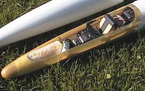
Bill Watson used this refined installation in his "Emerald" sailplane as shown above and in the heading photo. Modern piezo-electric gyros are small enough and draw little enough current to be easily practical in thermal sailplanes. The gyro is the small rectangular solid located in the forward fuselage just behind the two servos as shown in the close-up figure. It is tilted back 30 degrees from the yaw-only, horizontal orientation. The specific gyro Bill used is marketed in the United States by Hobbico as the "Airplane Piezo Gyro Stabilizer". This is sold by Tower Hobbies as stock number TH1919 for $129.99.
Flight Testing
Bill Watson test flew the gyro in his Emerald sailplane. This model is a typical composite 6-servo model. Adjustment of the gyro gain does indeed control the spiral stability of the model. At zero gain, the behavior of the model is naturally unchanged. As the gain is increased, less and less "top aileron" is required to maintain a constant bank angle. At some point the spiral stability becomes neutral and no aileron bias is required. Beyond this point, spiral stability becomes positive, with bottom aileron required to hold the airplane in the circle.
At less than neutral gains, the spiral characteristics are still unstable. This means that the pilot must continue to make active inputs to control bank angle, and a fixed aileron setting leads to a roll departure or increased bank angle and speed. At neutral stability the model tends to stick at a constant bank angle with zero aileron input, but the bank angle may wander around a bit. With positive stability, the model holds a constant bank angle that is dependent on the aileron stick deflection, and tends to return to this bank angle if upset.
Bill Watson adds:
For normal thermal flying a sensitivity of medium to medium-high works well. But in rough, gusty air the changes in yaw rate tend to roll the glider out too much. The model tracks better through turbulence with lower gain. For straight line cross-country flying, maximum gain should be best.
At approximately neutral stability, no odd behavior was observed in any flight regime. Precise circling was possible at low flight speeds.
Conclusions and Closing Remarks
Spiral stability of 6-servo R/C sailplanes can be augmented with a rate gyro. This permits improved control of bank angle at lower airspeeds with much less pilot workload.
Perhaps other pilots who try this idea can add their flight test reports to this one so that a broader base of information can be shared.
References
- Beron-Rawdon, B. "Dihedral", Model Aviation Magazine, August through November, 1988.
- Beron-Rawdon, B. "Spiral Stability and the Bowl Effect", Model Aviation Magazine, September and October, 1990.
- Beron-Rawdon, B. "Calculation of Equivalent Dihedral Angle" in Michael Shellim’s R/C Soaring web site, rc-soar.com, January 2000