
Digicam RC to Serial Interface
 Here are the construction notes for my digital camera interface which was used for the photographs in my Aerial Photography by R/C article.
The unit is driven by one output of an R/C receiver and sends commands to the camera via a serial link.
The interface has been tested with the Olympus C400L, D340 and C840L digicams. Other digital cameras share the same Fujitsu chipset and the interface may work with those too. For more information on cameras and protocols, see http://www.average.org/digicam/cameras.html
Interface Description
The key component of the interface is a Stamp BS2 microcontroller available from Parallex Inc (http://www.parallaxinc.com). The Stamp contains a Stamp Basic interpreter, some memory, I/O ports, and an RS 232 interface (which is also used to download programs from a PC). Stamp Basic contains high level commands for measuring square waves, serial comms etc. The unit runs on 5V. All these factors make it ideal for an R/C project.
In operation the interface monitors pulses on one receiver channel. When a state change occurs (following a switch being moved on the transmitter), the interface generates a command string which it outputs to the camera via the Stamp's RS 232 port. Alternatively the interface can trigger the camera at regular intervals without an RC link.
The prototype was powered by the receiver battery.
Features
Interface operating modes are as follows:
- R/C Mode,Single-shot - by toggling transmitter control from off to on.
- R/C Mode,Time lapse - tx control left on. Trigger intervals variable in steps between 10 secs - 1 hr
- Standalone Mode - Time lapse only as above.
Configuration is via switches on the unit.
Construction Overview
Some basic knowledge of R/C systems and Basic programming is required.
To make the unit you will need a Stamp BS2 development kit and some components as listed below. Stamp details are at http://ww.parallaxinc.com.
You will also need to download the code. Two versions are available:
- Stamp BS2 Cam Interface code v1.1 - without resolution control.
- Stamp BS2 Cam Interface code v1.2 - with resolution control.
Thanks to Gary Thurmond for these enhancements to my original v1.0 code.
Parts List
- Stamp BS2 Development kit
- 2 x 220 ohm resistors
- 1 x 22k ohm resistor
- 8 x 10k ohm resistor (or use suitable SIL package).
- 1 x red led
- 1 x green led
- Cable for RS232
- Plug to fit cam RS232 port (depends on camera model)
- Servo cable and plug
- Single-sided perforated printed circuit board
- 8-way DIL switch
- Jumper wires (old resistor wires will do).
- DIL carrier for BS2
- Cable tie
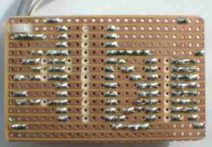
Construction Notes
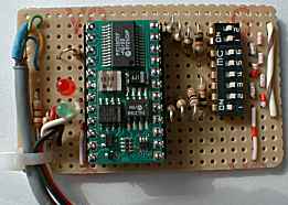
Refer to the pictures and schematic.
I/O pins 0-7 (i.e. BS2 pinouts 5 – 12) are wired identically to a switch and pull-down resistor, only the connections for pin 0 are shown. Note that the wiring could be made a lot simpler - and the package shrunk - by using a SIL package for the pull down resistors connected to I/O pins 0-7 (see picture of Gary Thurmond's unit below). This would remove a lot of the jumper wires. I haven't shown this 'cos I didn't build it like this!
If configurability is not required the board could be shrunk even further by leaving out the switches and associated resistors - the code would have to be edited however.
If using more than four cells, connect the battery +ve to the Regulator Input (pin 24).
I/O pins
| IO Pin(s) | Function |
| 0-5 | TimeoutVal 0 - 127. Pin 0 is LS bit. All switches OFF = 0, all switches ON=63 |
| 6 | Multiplier for TimeoutVal (pins 0-5) ON - timeout = TimeoutVal minutes OFF - timeout = TimeoutVal x 10 seconds |
| 7 | Mode OFF=R/C ON=Standalone |
Note: the pin number on the Stamp package = I/O pin + 5
Schematic

Feedback
If you build one or even use it as a basis for your own design, please share your experiences and perhaps send in some pictures. I'd be most grateful for any comments or suggestions - please email me at the address at the bottom of the page.
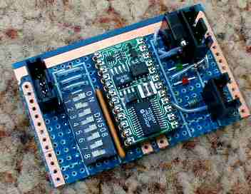
Gary Thurmond
Here's a photo of Gary's unit. Note the SIL resistor array between the switches and the Stamp. Gary was responsible for various bug fixes and enhancements to my original code.
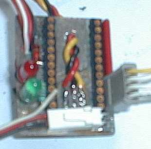
James Ropiteau
James Ropiteau of France has a minimalist version. Photo taken through a milk bottle?
"My stamp is put together on 3cm x 4cm PCB and weight 26 grams. No dip switch, no reset and still a 6V regulator (1.5 A) . With your software picture every 15s on 840L.".
(The min interval should be greatly improved with v1.1 of the software - MS.)
Disclaimer
This was an experimental project. I will not be held responsible for any damage resulting from any errors in the design. If it blows up in your face or damages your camera, then tough! Treat it as a prototype system, read up on the stuff you don’t know, and check your connections carefully.
Acknowledgements
Eugene Crosser for his camera protocol page. Dave Woods, for recommending the Stamp micro controller in the first place. Gary Thurmond for his invaluable code fixes and enhancements. Allan Teo of Singapore for his interest which led to this document. Apart from Dave Woods, who is a member of the ISA, I have only "met" the other gentlemen through the Internet. Actually not quite true, I have also met Allan (who introduced me to the culinary delights of "hawker centres" in S'pore), but that was also through initial contact on the Net!