Tutorials : mc4000 - Flight Modes, T switches, and Presets
Introduction
The 4000 supports "flight modes". Let's look at this important topic in more detail.
Flight Modes overview
Flight modes provide a quick way for the pilot to switch between different control settings during flight. For example with a tow-launch glider, different elevator trim and travel may be required for launch and landing. By switching between flight modes, the pilot can quickly call up the correct settings.
Which Adjustments are Stored per Flight Mode?
The Controls Reference shows all the control settings which are be stored per flight mode. When altering any of these control settings, the active flight mode is displayed at the top of the screen. Remember to switch to the relevant flight mode before making an adjustment to ensure it's stored in the correct flightmode.
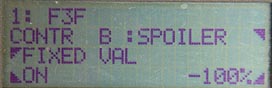
Adjust Controls menu for Spoiler/FIXED_VAL.
The top line shows the active flight mode ('F3F') to which this adjustment applies
Flight mode states
There are five flight modes available on the 4000. Each flight mode has a state either On or Off. When you create a new model, the default flight mode (flight mode 1) is automatically On. By default, other flight modes Off. Any control adjustments are therefore initially automatically assigned to the default flight mode.
To use any flight modes 2 - 4, each must each be assigned to a switch, and the state of the corresponding switch determines whether the flight mode is On or Off. Unassigned flight modes are Off by default.
Transfer (T) switch overview
A typical scenario is to have three flight modes, each of which is selected according to the position of a three position switch.
To use a 3-position switch for this purpose, it is necessary to first create a transfer ('T') switch. A 'T' switch allows each position of a three position switch to perform a different function. It does this by treating each position as a two-position 'virtual' switch. Like a real switch, each 'virtual' switch is either On or Off.
To set up a transfer switch T1, follow these steps:
- Enter the Assign Switches screen
- Select the T1 switch from the list of switch types
- Select the real switch SO1 or SO2 etc. (must be a 3-position switch)
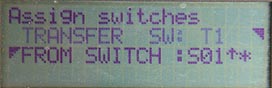
Transfer switch T1, based on 3-position switch SO1
Once a transfer switch has been created, you will find three 'virtual' on/off switches in the menus, designated Tn-1, Tn-2 and Tn-3. These represent the bottom, middle and top positions of the 'real' 3-position switch. In effect, each position of the 3-position switch is represented by its own 'virtual' on/off switch.
A typical configuration of virtual switches would be:
- Physical Switch DOWN:
Virtual switches T1-1 is ON, T1-2 Off, T1-3 off. - Physicial Switch MIDDLE:
Virtual switches T1-1 Off , T1-2 ON, T1-3 off. - Physical Switch UP ,
Virtual switches T1-1 Off, T1-2 off, T1-3 ON
As with real switches, the state of a virtual switch is indicated by an asterisk (*). As you move the real switch, you should see the asterisk appear or disappear for each virtual switch.
You can reverse the 'sense' of a virtual switch by pressing the R button in the appropriate menus. Taking T1-1 for example, after reversing it, it would be active when the switch is in the up or middle positions, and inactive when it's down.
Priorities
When multiple flight modes are used it is possible that two or more may be on at the same time. To resolve this conflict the system uses a flight modes 'priority' to determine the active flight mode. The priority of a flight mode is the same as its number e.g. flight mode 1 has a priority of 1, flight mode 3 has a priority of 3 etc.
Since the default flight mode (flight mode 1) has the lowest priority, it will always be over-ridden if another flight mode is On.
Example with flight 2 - 4 assigned to switches, and flight mode 5 unassigned. If flight modes 3 and 4 are both selected, we have the following situation:
FM 1: ON (DEFAULT always On)
FM2:  Off (via switch)
FM3:  ON (via switch)
FM4:  ON (via switch)
FM5:  Off (UNASSIGNED)
Then in this case, FM4 is the active flight mode as it has the highest of any of the On modes.
Setting up a flight mode
Having set up a T switch, we're ready to set up some flight modes. This is done in the Flight Phase menu. The figure in the top left corner is the priority. The activation mode is shown in the bottom right corner. The bottom left corner specifies the transition time.
In the following example, we have have already set up a T switch. We use it to select between three flight modes 'F3F', 'Thermal' and 'Landing".
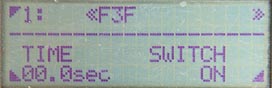
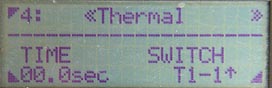
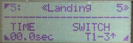
Flight modes F3F (priority 1), Thermal (4) and Landing (5), all driven by 3-pos switch T1.
Note:
- Thermal mode is activated by virtual switch T1-1 (3-pos switch DOWN)
- Landing modes is activated by virtual switch T1-3 (3-pos switch UP).
- F3F is always On (remember, because it is the default flight mode, you can't set it to a switch). Since it has the lowest priority of 1, it will only be active when the other two flight modes are not active, i.e. when he 3-pos switch is in the MIDDLE position.
To summarise:
- 3-pos switch up - landing
- 3-pos switch middle - F3F
- 3-pos switch down - thermal
Adding a fourth Flight Mode
Suppose now we want to add a fourth Aerobatic flight mode. We've already used a three position switch, so we must use a second switch for this. Let's use a 2-position switch SO2.
Let's have Aerobatic mode override F3F, but not override Thermal and Landing modes. Aerobatic therefore needs a priority between 1 and 4, so we'll use flight mode 3.
This is the screen for flight mode 3:
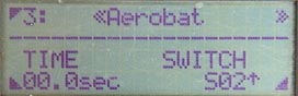
Aerobatic flight mode, priority 3, driven by SO2
So now
- 3-pos switch up - landing
- 3-pos switch middle, SO2 down - F3F
- 3 pos-switch middle, SO2 up - Aerobatic
- 3-pos switch down - thermal
Presets and FIXED_VAL
You may notice in the controls reference, that some controls have a FIXED_VAL setting. This is available for throttle, spoiler, flap and tow-release and some other controls. FIXED_VAL is a simple way of implementing what in other R/C systems are called presets.
Crucially, FIXED_VAL can be activated per flightmode. So for example, a flight mode could be setup to set a particular control to a fixed position, over-riding the actual stick position.
How to set up FIXED_VAL
The procedure for setting up FIXED_VAL is:
- Enter the Adjust Controls menu
- Select the control (e.g. Spoiler, Flap, Towhook etc.)
- Switch in the target flight mode (the one you want the FIXED_VAL setting stored in).
- Choose the FIXED_VAL option.
- Set the FIXED_VAL value between -100 and +100
- Set the FIXED_VAL activation mode to On, Off, or a switch.
FIXED_VAL Activation mode
Setting the Activation mode to ON means that the control permanently takes on the fixed value specified by the user.
Setting it to OFF means that the control operates normally, via the widget assigned to it.
You can also activate FIXED_VAL via a switch. However, it's more common to set the activation mode to On or Off, and to select a particular FIXED_VAL setting via flight mode.
Putting it All Together - Flight modes and FIXED_VAL
Consider a glider with two flight modes. We wish to enable the spoilers in landing mode, so that they can be operate by the stick, but disable them in F3F mode (i.e. hold them always in a fixed position).
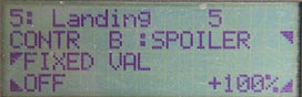
Below is the Adjust Controls menu, for the Spoiler control. The shots below show the FIXED_VAL settings for the Landing and F3F modes.
Setting a preset to disable spoiler in F3F mode
- in Landing mode, FIXED_VAL is OFF, so the spoiler works off the stick as normal.
- in F3F mode, FIXED_VAL is ON. the value is set to -100, which corresponds to the 'stick-forward' position. In other words, the spoiler remains closed, and inactive in this flight mode.
Trim Offsets are not done using presets!
A bit of a diversion here... suppose your model requires a bit of up elevator trim during the launch phase. Should you program this using FIXED_VAL? Emphatically NO (I've seen some bizarre methods of achieving this trivially simple task!).
To set a trim offset,
- Switch the relevant flight mode
- Enter the Adjust Control menu
- Adjust the elevator's CENTRE attribute.
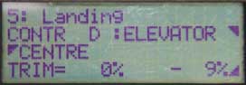
Trim set to -9% in landing flight mode. This added to the trim lever position, currently centred.
The CENTRE attribute is added to the trim lever position to provide a trim offset specific to the flight mode.
Now, let's see a few genuine examples of presets using FIXED_VAL, and how they can be combined with flight models...
Example flight mode scheme
Let's further explore flight modes, by looking at the setup for a glider. This time, we will consider just three flight modes Launch, Normal, and Landing (we'll drop the Aerobatic mode). Here are some typical preset and trim settings which are easily implemented with flight modes.
| Flight Phase | CONTROLS | ||
| Spoiler | Flap | Elevator | |
| Launch | Goal: Disable spoiler Action: Spoiler control: FIXED_VAL mode = ON, FIXED_VAL value = 100 |
Goal: Control flaps via lever Action: Flap control: FIXED_VAL mode = Off (the default). |
Goal: add some up-trim Action: Set Elevator CENTRE attribute to suit (this will be added to trim lever position). |
| Normal | As above | Goal: fix flaps at zero camber, and deactivate flap lever Action: Set flap FIXED_VAL mode=ON, value = zero |
Goal: Use default elevator trim Action: set Elevator CENTRE = zero |
| Landing | Goal: Enable spoiler stick |
As above | As above |
Using the Flight Mode switch as a control switch
Flight mode switches are activated by 'secondary' switches, which cannot be used to directly control a servo (well not easily). However as we shall see there is a workaround. Why should this be necessary at all though? The best way to illustrate this is by an example.
Suppose that you have a glider with a tow hook release servo activated by a switch, say 'G'. Suppose also that you have a flight mode switch SO1 to switch between Launch and Normal modes. Typically when launching, you would start in Launch mode (SO1), and lock the tow hook (G). At the top of the line, you'd release the tow hook (G), then revert to Normal mode (SO1). Each phase change requires two switches to be flicked almost in parallel. Wouldn't it be easier if only one switch could be used for both flight mode selection, and tow hook release?
Well, there is a way to do this. Simply assign a FIXED_VAL values for the Tow hook control, for all flight modes. Then the Tow hook servo is then controlled solely by the flight mode switch (even though it is assigned to G).
What Flight Modes Can't Do
Flight modes affect adjustments at the control level, like DIFF, EXPO, FIXED_VAL etc. They cannot be used to select different curves, centres etc. at the servo level - at least not directly. However - you've guessed - there is a workaround for this. I'll leave this for another time.
(I think 'workaround' is not the right term - it suggests that the designer of the 4000 somehow left out a feature. In fact he just provided all the right functions to allow reasonably simple setting up, while allowing you - the user - to use your creativity should you need to.)