Performance Analysis of a Family of R/C Thermal Sailplanes
Concept
 A theoretical study was made to evaluate the effect of minimum sink rate, span, and aspect ratio on the performance of a family of conventional radio controlled thermal sailplanes.
The idea is to develop data which permits the designer to choose a promising starting point with respect to span, aspect ratio, and weight to achieve a performance target.
18 plots are presented which compare the performance of 104 sailplanes. The Selig-Donovan SD7037 is used for all of the planes.
A small selection of tables, graphs and 3D views is shown here. To see all of them download Excel file (40 KB)
Description of the Airplanes
 A theoretical family of notional, conventional sailplanes was created. Five spans were chosen: 60, 80, 100, 120 and 140 inches, corresponding to approximately 1.5, 2.0, 2.5, 3.0 and 3.5 meters. Seven aspect ratios were used: 6, 8, 10, 12, 14, 16 and 20. These values encompass the vast majority of R/C thermal airplanes.
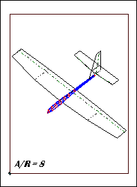
A conventional streamlined fuselage is assumed. Following common practice, fuselages on the larger planes are a little bulkier than on the smaller models, relative to their size. The wetted area of the fuselages is 86, 145, 216, 300 and 396 square inches for the five wingspans. Figure 1 shows the 300 square inch fuselage on the 120 span model.
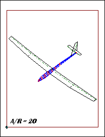
The fuselage length was set to provide a moment arm equal to 0.28 wingspans for both the horizontal and vertical stabilizers. This is a conventional value. Horizontal tail volume was held constant for all models at 0.4. Vertical tail volume was maintained at 0.02. These typical values adjust the tail size with aspect ratio as seen in Figures 1, 2 and 3. The model geometry was generated using "Plane Geometry", a spreadsheet template. See Reference 1.
 The weight of each model was adjusted during performance estimation to provide three discrete values for minimum sink rate: 1.0, 1.25 and 1.50 ft/sec. These values encompass the range of typical thermal R/C sailplanes and also define discrete classes of models. Models which achieve sink rates of 1.0 ft/sec are true floaters, slow, graceful and able to work very light thermals. These planes typically thermal at 20 ft/sec and have wing loadings of about 7 oz/ft2. Models with minimum sink rates of 1.25 ft/sec are the mid-range of quality thermal sailplanes, thermalling at 25 ft/sec with wing loadings about 10 oz/ft2. Lastly, models which achieve a minimum sink rate of 1.5 ft/sec favor speed above light air thermalling performance, circling at about 30 ft/sec with wing loadings of 16 oz/ft2.
All of the models use the SD7037 airfoil. This is an excellent and popular modern thermal sailplane section which works quite well even at low Reynolds numbers. See Reference 2. No flap or reflex was used.
Performance Calculation
The performance of each model was estimated on the basis of lift and drag data presented in Reference 2.
A drag buildup was made of the wing, fuselage and tails. Wing drag is estimated on the basis of Reynolds number, lift coefficient and mean aerodynamic chord (MAC). No spanwise division and summation of the wing was performed. The MAC is assumed to be equal to 1.03 average chords, a typical value. Induced drag is simply based on an Oswald efficiency factor, e, of 0.95, a typical value.
Fuselage drag uses a fixed drag coefficient of 0.008 based on its wetted area, independent of Reynolds number. Tail drag is assumed to be 0.01 based on tail planform area, also independent of Reynolds number. Lastly, a extra drag ("fudge factor") of 0.002 based on the wing area is added in to account for intersections, excresences and so on. This increases the model drag roughly 10% Trim drag is ignored.
The weight of each model was adjusted to give a minimum sink rate of 1.0, 1.25 or 1.5 ft/sec. A glide polar for each finished model was generated, and from this various values are extracted as presented in the figures.
Drag data for the SD7037 is a little twitchy, especially at lower Reynolds numbers. This is reflected in some of the plots.
Discussion
Six plots are presented for each model. They are:

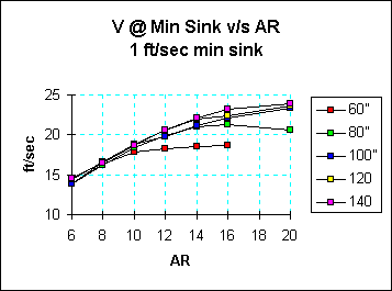
- V @ Min Sink. This is the airspeed the model flies when it is sinking most slowly. This is the approximate speed at which the model should be thermalled. Slower is generally better here since lower speeds mean smaller circles and more precise placement in the thermal. This is essential for hand launch models.
- V @ L/D Max. This is the airspeed the model flies when it is gliding the flattest. This would be the speed to fly between thermals on a very weak day or when just putting about. A higher speed is generally desirable since when gliding between thermals there may be sink, or you may wish to cover ground upwind.
- V @ 2x Min Sink. This is the airspeed that results from cruising with a sink rate of twice the minimum sink rate, in this case either 2.0, 2.5 or 3.0 ft/sec. This is an indication of the speed of the model when moving rapidly between thermals or escaping sink. Faster is definitely better here.
- L/D Max. This is the maximum lift to drag ratio, or the glide ratio. It is an indication of the basic efficiency of the model. More is better.
- Weight. This is the weight the model must be to achieve the minimum sink rate capability. Weight is somewhat irrelevant to sailplanes except that it has a bearing on launching characteristics and structural soundness. More on this in a bit.
- Wing Loading. This is just the weight divided by the wing area, presented as a reference value.
Some examples of how to use the plots:
You want to design a typical 120 span model to achieve a minimum sink rate of 1.25 ft/sec. What is the best aspect ratio?
Well, you are looking for good interthermal speed (V@2X) with acceptable thermalling speed. You can see from the V@2X plot that there is no point in going to AR=20 since it is no faster than AR=16. How does AR=14 compare to AR=16?. V@2x is down about 3%, but thermalling speed is down about 5% from 28 to 26.5 ft/sec. AR=12 is even slower in the thermal and in-between thermals. The trade might depend on how important low thermalling speed is compared to fast interthermal glides. If you fly in calm weather with small thermals, the low thermalling speed is important. If you fly in windy weather, the higher speed of the AR=16 might be the best bet. But before you decide, check the weight plot! The AR=12 model may weigh 5.5 pounds, an attainable value. The AR=16 model must weigh less at 5.2 pounds. This may be difficult to achieve if strong launches are required since the root chord of the model would be only about 8.5 inches.
You want to make the ultimate floater model for those light, calm days.
What should it be? A first look at the V@2X plot shows that the AR=16, 140 inch span model the best. It thermals at only 23 ft/sec, plenty slow. So this would be a great plane for a master builder since it could weigh no more than 4.6 pounds! Also, there may be a problem thermalling this plane at higher bank angles as its circle radius is small compared to the wing span. Substantial top aileron must be held to keep the low wing up. A rough rule of thumb is that the thermalling airspeed should be no less than 2.5 times the wing span. That is, a 10 ft span model should thermal at at least 25 ft/sec. This is a rough measure, but I have had problems with models much below this number.
So say we come down in size to a 100 inch span model to get better handling. Here, AR=12 is the clear winner since higher aspect ratios yield no improvement in interthermal speed. And the thermal speed of 20 ft/sec is just about 2.5 times the span! Note that this model is 6.5 ft/sec slower than the big model above between thermals. Note also that this model must weigh about 2.1 pounds, an achievable figure for an expert builder, but likely to be fragile...
How about a duration model for strong and windy conditions?
Better go to the 1.5 ft/sec charts! Clearly the best performer is the biggest, highest AR model. At 23 oz/ft2 it will tricky to launch on calm days and may require careful construction to meet the 9.5 pound weight target. Precision landings could be a problem, too. But what a glide with an L/D of 25!
What about a hand launch model?
These are constrained in the US to 60" span. Since they fly close to the ground in light, small thermals, low sink rate and low thermalling speeds are critical. What is the best AR? Going to the 1.0 ft/sec charts, it is clear from the V@2X chart that there is no point in going above AR=10, and AR=8 is almost as fast. AR=8 thermals significantly slower at 16 versus 17.5 ft/sec so this is an advantage for the AR=8. AR=6 takes a pounding in the interthermal cruise speed, so it is no good. So the optimum looks to be someplace between 8 and 10. Note that the weights and wing loadings are in line with current practice at about 12 ounces and 4 oz/ft2.
What Is Going On Here?
This study illustrates the trades between Reynolds number, aspect ratio and wing loading. High AR wings benefit at lower speeds due to their reduced induced drag. At higher speeds this advantage disappears nearly entirely except that, for a fixed minimum sink rate, the higher AR wing can fly at a higher wing loading so it is still better at higher speeds, generally.
On the other hand, higher AR wings suffer from lower Reynolds numbers and consequent higher profile drag. This is most important for smaller and lighter (slower) planes, so as the planes diminish in size and speed, the optimum AR becomes smaller. At some point, the higher AR wing provides no wing loading advantage to achieve a given minimum sink rate, so this, combined with increased profile drag due to lower Reynolds number, hurts the high speed performance.
Predictions for Future Trends
It would appear that current contest airplanes are close to optimum in terms of aspect ratio.
Some of the larger models might benefit by higher aspect ratios, but this is currently constrained by structural and weight considerations. As employment of composite materials becomes more sophisticated I anticipate a move to slightly higher aspect ratios. Judging from the very low flexure of modern contest sailplane wings it would appear that the wing structure is worked to relatively low stress values. Improvements in this structure will result in greater strength and lighter weight, leading to lower sink rates and slightly higher aspect ratios.
Fuselage wetted area continues to play a significant part in the drag of modern R/C sailplanes. As improved materials make their way into fuselages they will be reduced in cross section, especially aft of the wing. This will benefit the higher aspect ratio airplanes more than lower aspect ratio planes since a given reduction in fuselage wetted area is a bigger percentage of total wetted area.
References
- "Plane Geometry" software by Envision Design
- Airfoils at Low Speed, Selig, Donovan, Frasier. Soartech 8. Herk Stokely, 1504 North Horseshoe Circle, Virginia Beach, VA USA 23451
Copyright © Blaine Beron-Rawdon
