
Introduction
Part of the fun of reviewing radios is trying to eak out all the features - and occasionally bugs - in a new transmitter. Not so much fun, however, is having to fiddle with servos and batteries all the time!
ServoSim
With this in mind, I have made a little gizmo for exploring a transmitter's programming on the PC screen.
The heart of the system is an interface which goes between the tx DSC (trainer) socket and a Windows PC.
Firmware
The interface is based on a PIC 16F628 microcontroller. The PIC monitors the trainer sigmal from the transmitter. In most systems, this is a series of short (~300 microsecond) negative going spikes. The pulse intervals are encoded into 3-character hex strings and sent to the PC over a serial link.
The PIC firmware is written in assembly language.
PC Software
A Visual Basic program running on the PC monitors the serial signal from the interface, and decodes the pulse intervals.
- Choice of bargraph or servo display
- Auto-adjusts for MPX and non-MPX neutrals
Supported Tx's
The system has been tested with the following tx's
- Multiplex mc 4000
- Multiplex mc 3030
- Futaba FF7
- Spektrum DX-7
Hardware
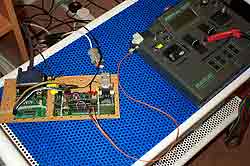 Version 1 (left): The picture above shows the EPROM programmer and Lab X2 dev board.
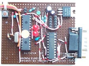 Version 2 (left). This is on a board 70mm x 60mm.
Version 3 is smaller still and uses just 9 components (no picture available)
Screenshots
All shots show "Bargraph" display mode
Switch on the Tx. Note that the servo's are not quite centred, so...
Set a new baseline. No movement until...
The Aileron stick is moved. The wing servos (along the top line) respond.
So do the V-tail servos, due to combi mix.
Menus
This is the "Mark" menu for setting a new baseline.
The Options menu selects MPX or Futaba/JR/Hitec neutrals.
You can select a number of viewing options.
Status
The system is under development