Tips and Tricks
Batteries and Charger
With the Ikarus-supplied 7-cell 250 mAH Sanyo NiCd pack
I get about 4 minutes per charge. I use a Robbe Infinity 2 charger, this is an
excellent unit. On the Auto setting, it
takes about 20 minutes to fully charge. With two packs you can fly on one pack
while charging the other.
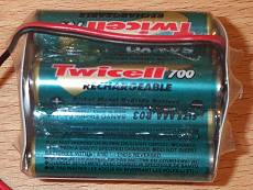 As of April 2001, I've made up an 8-cell Sanyo
Twicell 700 mAh NiMH pack. Flight times in the order of 7-8 minutes + 1
min ground effect. When charging NiMH, I set the delta peak
detection to Sensitive and disconnect
immediately after full charge is reached (conventional wisdom is that NiMH don't like
any kind of overcharging, including trickle charge). As of April 2001, I've made up an 8-cell Sanyo
Twicell 700 mAh NiMH pack. Flight times in the order of 7-8 minutes + 1
min ground effect. When charging NiMH, I set the delta peak
detection to Sensitive and disconnect
immediately after full charge is reached (conventional wisdom is that NiMH don't like
any kind of overcharging, including trickle charge).
More recently still, I've started setting the charge current
manually, to 700 mA, still with peak detection, this also works
well. Interestingly, even on the manual setting, the Infinity
still goes through a routine of ramping up the current from zero to
700 mA every couple of minutes, so even on the manual setting it
appear to be doing some clever monitoring.
Fixing Things
The model is remarkably resistant to crashes,
but inevitably things break or wear out. Different folks seem to have
different things go wrong, here's a list of things that I've had to
deal with.
Landing Skid
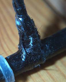 My landing gear struts tend to break at
the base. I use carbon tows to strengthen the joint. My landing gear struts tend to break at
the base. I use carbon tows to strengthen the joint.
Get a few tows about
2" long, spot glue one end to the strut, wind the other end round
the skid, and spot to the other side of the strut. Then apply cyano,
wait to dry and cut off the excess carbon.
Very effective. (I got the
idea from another page, can't remember but thanks to the author
anyway!).
Rotor Bearings
These tend to fly off all over the place and are
difficult to find. I carefully cyano the bearings to the hub, this
helps but occasionally the bearings slip off again, possibly because there's a film of oil on the inside of the
bearings. I'd rather leave the oil on and put up with the occasional
hassle.
Boom Attachment
Here's a mod which has saved me a lot of
grief.
Instead of gluing the
boom to the main and tail rotor assemblies, I now rely solely on a
friction fit. This has two major benefits (a) it allows the tail
rotor assembly to twist in the event of a crash, absorbing some of the
impact energy and reducing the risk
of damage to the boom. (b) the boom can be replaced very quickly if
necessary.
Fixing Cracks in the Boom
Cracks in the boom are best fixed with slow-setting
cyano, rubbed into the damaged area. I gave up using using low viscosity cyano, as it goes all over the
place including the inside of the boom where it can end up playing
havoc with the tail rotor motor power cable, or worse it can even
dribble down the boom onto main rotor assembly, as I've discovered!
Tail Rotor Pinion
The plastic motor pinions tend to start slipping after
a while. To prolong the period between re-gluing, roughen the shaft
first with wet/dry paper. I use slow setting cyano to hold the pinion
in place.
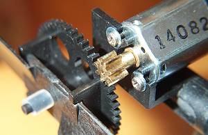 At Dortmund Ikarus were supplying replacements which
had metal pinions, I bought one and have had no trouble. The problem
will be transferring the pinion to another motor when this one wears
out...
At Dortmund Ikarus were supplying replacements which
had metal pinions, I bought one and have had no trouble. The problem
will be transferring the pinion to another motor when this one wears
out...
Removing a Brass Rotor Pinion
Thanks to Kris Manbeck for this tip:
To remove the brass pinion for use on
other motors, use a high powered soldering gun (about 100w), and a
small vice. Put the motor in the vice snug. Next heat the (brass)
gear with the soldering gun. While the gear is hot use a small pair
of needle nose pliers or a small flat screw driver and simply pry it
off of the shaft. Be carefull not to scar the teeth. If you use
pliers try to stay on the hub of the gear. for install on the new
motor. Freeze the new motor for a couple of hours (do not drop it
after it is frozen the glue for the magnets gets brittle and the end
bell is plastic they may crack on impact). Next heat the gear again
with the soldering gun, after the motor is good and frozen! Hold the
motor in hand or gloves. Do not use the vice. After the gear is hot
lay it on something that will not melt! Face down (hub toward the
motor) and press the motor on the gear. with the motor frozen
(contracted) and the gear hot (expanded) they should slip together
relatively easy. If it does not seem to work, do not pound the gear
on! It may damage the brushes or end bell as they are delicate. Let
the whole assembly set until cooled and thawed. ALSO be carefull not
to push the gear on to far it will rub the motor can and MAY
cause the washers inside to chew up the brushes if it pulls the
armature to far out. If the gear slips on too far, quickly pull it
out until it is free of the motor can, keep your pliers handy while
you attempt this.
Tail Rotor Motor
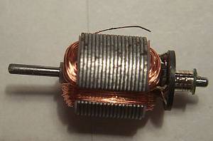 On
one occasion I found the tail rotor motor did not appear to be working
properly. I
dismantled it and found that one of the windings had broken at a solder
joint and had wedged itself
between the armature and the magnet.
The photo shows the damage. Note also the brush tracks on the
commutator. On
one occasion I found the tail rotor motor did not appear to be working
properly. I
dismantled it and found that one of the windings had broken at a solder
joint and had wedged itself
between the armature and the magnet.
The photo shows the damage. Note also the brush tracks on the
commutator.
As an aside, disassembling the motor is easy,
but putting it together again is another matter. The brushes are
very delicate. If the end bell becomes separated from the armature you
may as well toss the motor in the bin.

|